Reading Battery Voltage With Arduino Voltage Divider
Measuring DC Voltage using Arduino
Created on: 23 May 2013
Arduino analog inputs can be used to measure DC voltage betwixt 0 and 5V (on 5V Arduinos such equally the Arduino Uno when using the standard 5V analog reference voltage).
The range over which the Arduino can measure voltage can be increased by using two resistors to create a voltage divider. The voltage divider decreases the voltage being measured to within the range of the Arduino analog inputs. Code in the Arduino sketch is then used to calculate the actual voltage being measured.
This allows voltages greater than 5V to be measured.
This video shows the Arduino being used to measure various voltages:
Tin't come across the video? View on YouTube →
Principle of Performance
Input Impedance
A digital multimeter set up to measure DC voltage volition typically have an input impedance of 10MΩ or greater.
What this means is that the resistance betwixt the ii multimeter probes is 10MΩ or more than.
A high input impedance for a voltmeter (or multimeter on the voltage scale) is desirable every bit the higher the input impedance, the less probable the multimeter will influence or change the circuit being measured.
Measuring voltage across a component in a circuit with a multimeter that has an input impedance of 10M ohms, is the same equally connecting a 10M ohm resistor beyond the component.
If a voltmeter has a low input impedance, say 10kΩ and a voltage across a 10kΩ resistor is existence measured, the multimeter is effectively changing the resistor value to 5kΩ (two 10k resistors in parallel = 5k resistance). The multimeter therefore has inverse the circuit and possibly the voltage being measured.
So a loftier input impedance is desirable in our voltage divider circuit if the impedance of this "voltmeter" is going to influence the circuit being measured.
As a full general rule though, a high input impedance device will by and large pick up more than racket or interference (EMI) than a depression input impedance device.
Voltage Divider Circuit
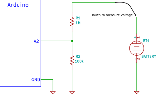
A voltage divider circuit consisting of two resistors in series volition carve up the input voltage to bring information technology inside the range of the Arduino analog inputs.
The circuit shown below will carve up the input voltage past eleven (from the bombardment as the example input voltage beingness measured).
The circuit with the detail values shown has an input impedance of 1MΩ + 100kΩ = 1.1MΩ and is suitable for measuring DC voltages up to almost 50V.
Precautions
Common Ground
If the Arduino is powered from an external power supply or a USB cablevision (i.eastward. not powered by a isolated battery or other isolated ability supply) the excursion may share a mutual ground or 0V connection with the circuit under examination.
If the GND connectedness of the Arduino is connected to any other part of the circuit under test except GND, so this is the same as shorting that part of the excursion to GND.
The GND of the Arduino is similar the negative or common (COM) lead of a multimeter, except that it should be considered to be permanently continued to the GND of the circuit nether test for safety, unless the Arduino or the circuit under test is completely isolated and "floating".
Input Protection
The resistor values in the circuit diagram above provide some over-voltage protection when measuring low voltages such as 5V, 9V or 12V. So if a voltage of say 30V is accidentally measured, information technology will not blow the Arduino analog input pivot.
Whatever voltage higher than about 55V could damage the Arduino. The point on the resistor divider network continued to the the Arduino analog pin is equivalent to the input voltage divided by eleven, so 55V ÷ 11 = 5V. In other words, when measuring 55V, the Arduino analog pin will be at its maximum voltage of 5V.
Providing this basic over-voltage protection is at the expense of not using the full 10-fleck range of the analog input ADC if only lower voltages are to exist measured, but changes of virtually 0.054V can still exist measured.
No other protection for voltage spikes, reverse voltage or voltages higher than 55V is shown in the circuit.
You can assist the Starting Electronics website past making a donation:
Whatsoever donation is much appreciated and used to pay the running costs of this website. Click the button below to make a donation.
Arduino Voltage Measuring Sketch
The sketch below reads the value on pin A2 of the Arduino. It provides some uncomplicated filtering by adding up 10 analog values from pin A2 sampled at 10ms intervals.
Afterwards taking 10 samples, the voltage is calculated using the boilerplate of the 10 sample values and sent out of the serial port for brandish on the Arduino Serial Monitor window.
Annotation that calibrated values are used in this sketch – these will need to exist inverse for your particular reference voltage and actual resistor partitioning factor, explained beneath.
/*-------------------------------------------------------------- Programme: volt_measure Description: Reads value on analog input A2 and calculates the voltage assuming that a voltage divider network on the pivot divides by 11. Hardware: Arduino Uno with voltage divider on A2. Software: Developed using Arduino i.0.5 software Should exist compatible with Arduino i.0 + Date: 22 May 2013 Author: W.A. Smith, http://startingelectronics.org --------------------------------------------------------------*/ // number of analog samples to accept per reading #define NUM_SAMPLES 10 int sum = 0; // sum of samples taken unsigned char sample_count = 0; // electric current sample number float voltage = 0.0; // calculated voltage void setup() { Series.begin(9600); } void loop() { // take a number of analog samples and add them up while (sample_count < NUM_SAMPLES) { sum += analogRead(A2); sample_count++; delay(10); } // calculate the voltage // employ v.0 for a 5.0V ADC reference voltage // 5.015V is the calibrated reference voltage voltage = ((float)sum / (float)NUM_SAMPLES * 5.015) / 1024.0; // send voltage for display on Serial Monitor // voltage multiplied past 11 when using voltage divider that // divides by 11. 11.132 is the calibrated voltage carve up // value Series.print(voltage * 11.132); Series.println (" 5"); sample_count = 0; sum = 0; } How the Code Works
Ten analog samples are taken using the post-obit code:
while (sample_count < NUM_SAMPLES) { sum += analogRead(A2); sample_count++; delay(10); } The sum or total of all 10 values added together are stored in sum. The variable sample_count keeps track of the number of samples.
Both variables are reset afterward calculating and displaying the voltage:
sample_count = 0; sum = 0;
The number of samples taken can be inverse at the top of the sketch:
#ascertain NUM_SAMPLES x
Don't brand this value too loftier or the sum of all the samples will exist besides big to fit in the sum variable.
The voltage is calculated using:
voltage = ((float)sum / (float)NUM_SAMPLES * 5.0) / 1024.0;
A calibrated value is used in place of five.0 in the to a higher place sketch – scale is explained later.
The 10 samples (sum) is divided past 10 (NUM_SAMPLES) to get the boilerplate value read.
5.0 is the 5V ADC reference voltage. 1024.0 is the maximum value that the ADC can take plus i (1023 + 1 or 2 to the power of 10 plus 1) 1023.0 can also exist used here.
This calculates the divided voltage – i.e. the voltage on the A3 pivot.
The actual voltage is calculated by multiplying the divided voltage past the sectionalization factor from the voltage divider network:
Serial.impress(voltage * 11.0);
The above line of code calculates the actual voltage and then sends it out the serial port for brandish in the series monitor window.
The sketch uses a calibrated value instead of xi.0 as shown here.
Books that may interest yous:

Calibrating the Arduino and Circuit
A more than accurate voltage could exist obtained by using a precision reference voltage for the ADC and using one% tolerance resistors or ameliorate.
Some other way to obtain a more than accurate reading is to calibrate the circuit. Calibration can be washed past measuring the actual value of the reference voltage and the actual values of the voltage divider resistors. These values tin can and so be used in the calculations in the Arduino sketch code.
Each Arduino and set of resistors would need to be individually calibrated because the voltage from the 5V regulator and the resistance of the voltage divider resistors will probably be slightly dissimilar for each Arduino and set of resistors.
Performing the Calibration
To perform the calibration, yous will demand a multimeter.
Calibrating the ADC Reference Voltage
First mensurate the 5V on the Arduino from the regulator (found on the Arduino 5V pin). This voltage is used for the Arduino ADC reference voltage by default.
At present put the measured value into the sketch as follows.
voltage = ((float)sum / (bladder)NUM_SAMPLES * 5.015) / 1024.0;
In the above instance, the voltage measured on the 5V Arduino pin was 5.015V.
You lot tin assistance the Starting Electronics website past making a donation:
Any donation is much appreciated and used to pay the running costs of this website. Click the push button below to make a donation.
Calibrating the Resistor Network
Connect a stable power supply, such as a 9V battery across the resistor network. Measure the voltage across both resistors together i.e. measure out the battery voltage.
At present measure out the voltage beyond the 100k resistor (R2) i.e. between Arduino pin A3 and GND.
The voltage divider factor is calculated by dividing the beginning voltage past the 2nd voltage or:
dividing cistron = input voltage ÷ output voltage
For example, if the first or input voltage measured is 10.02V and the 2d or output voltage is 0.9V, then the sectionalization factor is:
ten.02 ÷ 0.ix = xi.133
At present use this value in the Arduino sketch code:
Serial.print(voltage * 11.133);
If calibration is used, then 5% tolerance resistors tin can be used for the voltage divider.
As an Amazon Associate I earn from qualifying purchases:
kobayashientil1990.blogspot.com
Source: https://startingelectronics.org/articles/arduino/measuring-voltage-with-arduino/
0 Response to "Reading Battery Voltage With Arduino Voltage Divider"
Post a Comment